PPT Structural Mechanics 4 Shear Force, Bending Moment and Deflection
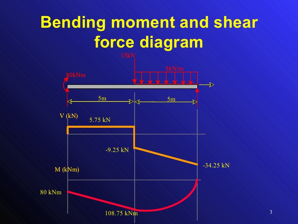
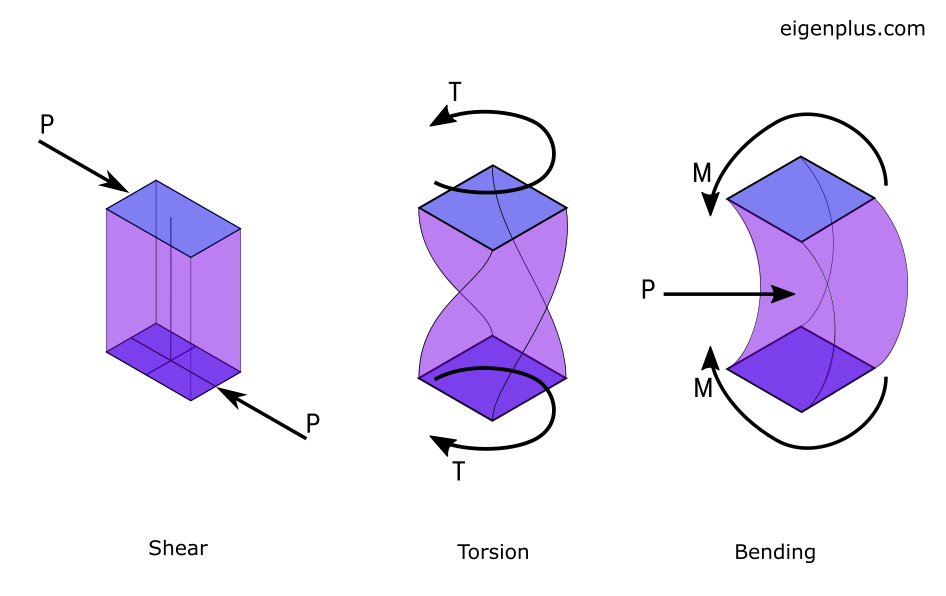
Beban pada sebuah balok cenderung menggeser balok dan juga membengkokkannya. Gaya geser (Shearing Force) pada suatu bagian balok adalah jumlah aljabar dari semua gaya luar tegak lurus terhadap balok di salah satu sisi bagian tersebut.Momen pembengkok (Bending moment) pada suatu bagian balok adalah jumlah aljabar dari semua momen gaya di salah satu sisi bagian tersebut.
Bending Moment
Flexural strength, also known as modulus of rupture, or bend strength, or transverse rupture strength is a material property, defined as the stress in a material just before it yields in a flexure test. [1]
What is bending moment? Understand in simple terms
A bending moment describes the internal force that leads to bending of a structural element such as a beam due to loading. In easier words, a bending moment refers to the tendency of a structural element to deform due to external loading (self-weight, snow, wind, people etc.).

Beam shear and bending moment diagrams sekajava
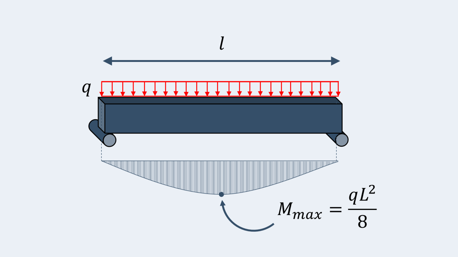
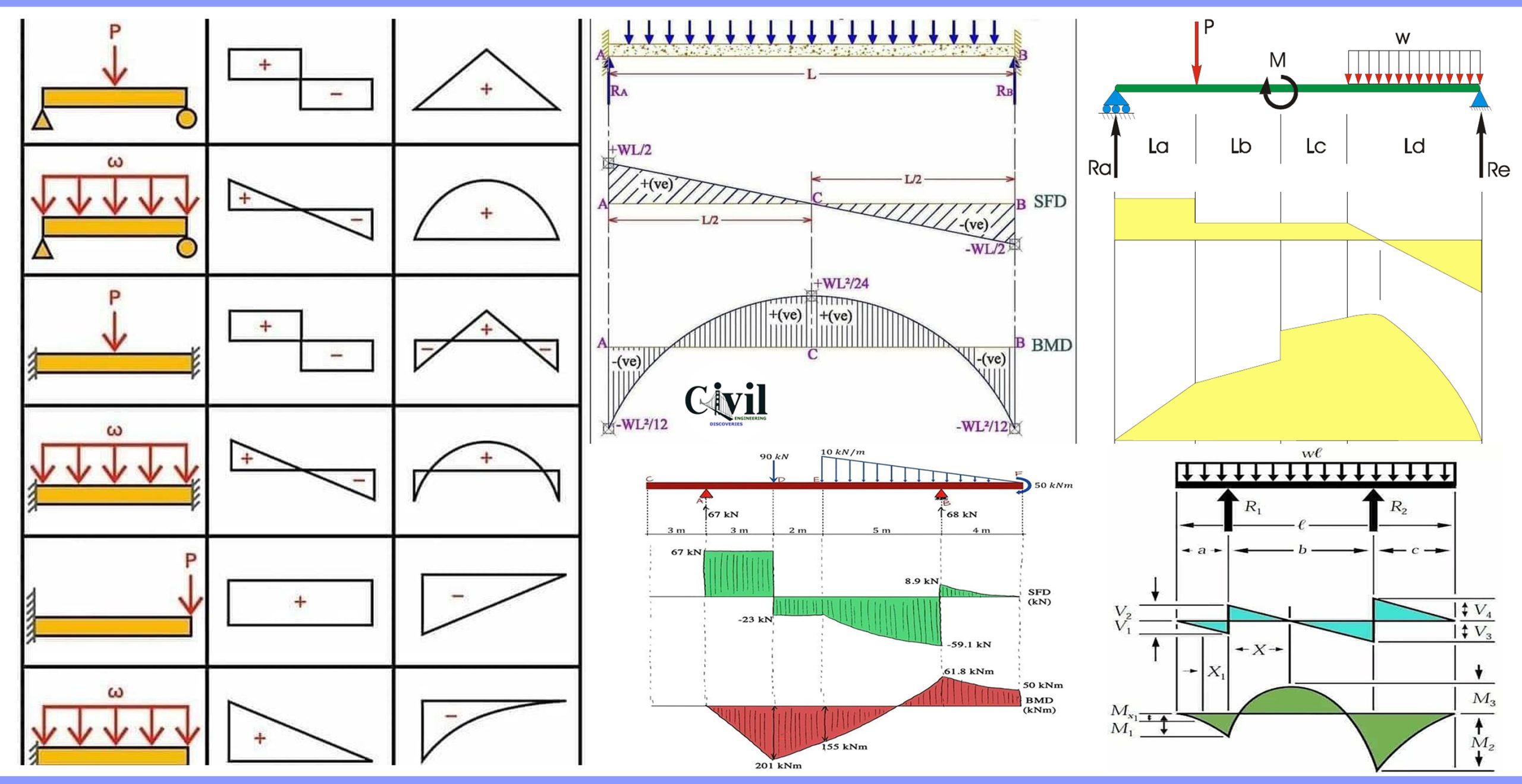
1. Uniformly distributed line load (UDL) - 4 Span continuous beam Bending moment and shear force diagram | Continuous beam with 4 equal spans | Uniformly distributed line load (UDL). Max positive bending moment ( x = 0.393 ⋅ l) M m a x = 0.077 ⋅ q ⋅ l 2 Positive bending moment M b c = M c d = 0.036 ⋅ q ⋅ l 2
PPT Shear Force & Bending Moment PowerPoint Presentation, free
This section covers shear force and bending moment in beams, shear and moment diagrams, stresses in beams, and a table of common beam deflection formulas. Contents Constraints and Boundary Conditions Shear Force and Bending Moment Sign Convention Shear and Moment Diagrams Bending Stresses in Beams Shear Stresses in Beams

Example of bending moment diagrams YouTube
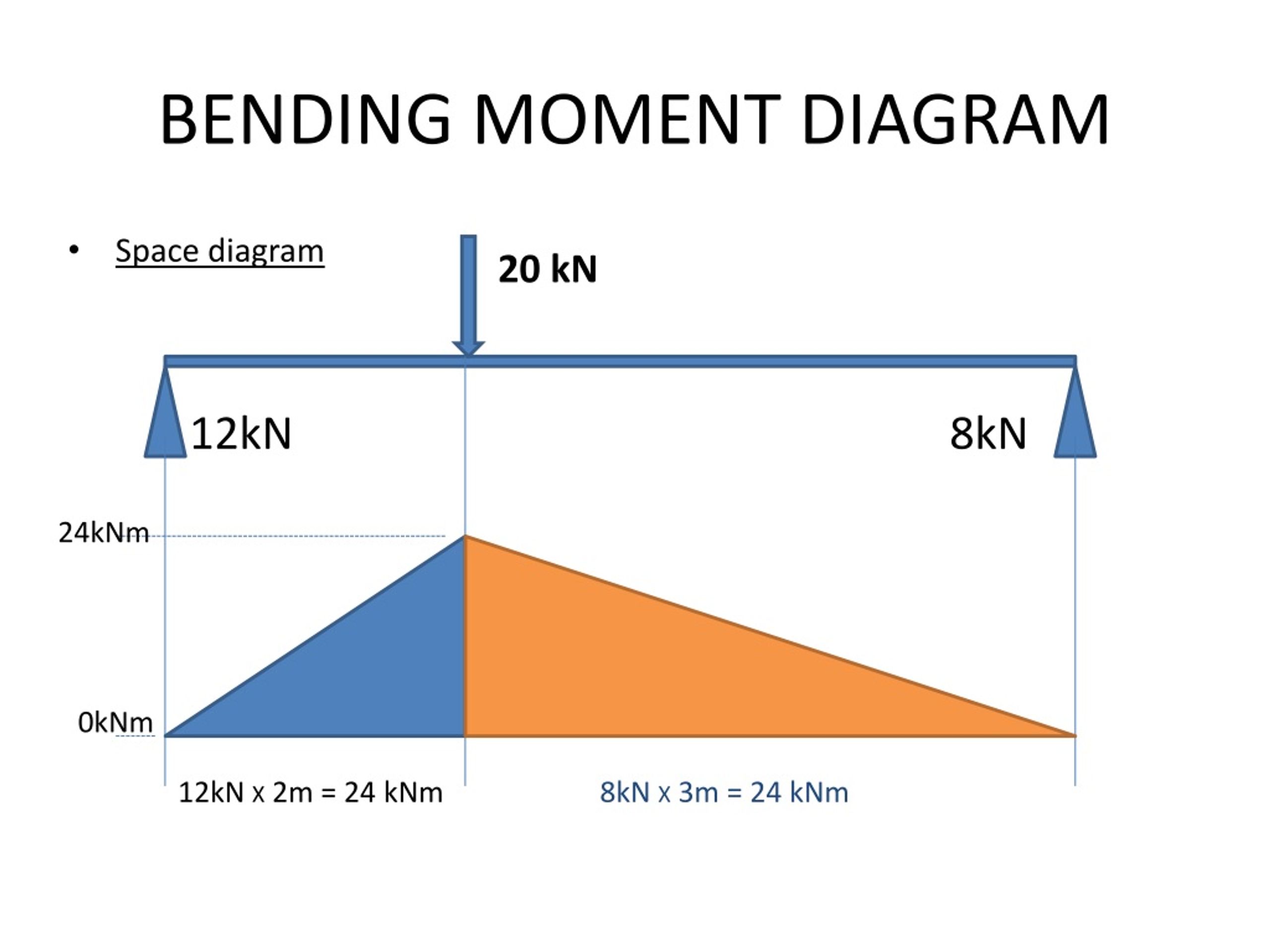
Bending moments visualized on a beam subjected to biaxial bending. How is Bending Moment Calculated. When transverse force is applied on a section of beam, the stresses produced will be known as bending stresses. Consequently, applied forces cause the bending moment which is commonly quantified as force x distance (kN-m).

Bending Moments
Step 1 | Draw a free body diagram. To correctly determine the shear forces and bending moments along a beam we need to know all of the loads acting on it, which includes external loads and reaction loads at supports. By drawing the free body diagram you identify all of these loads and show then on a sketch.
Bending Moment The Best Equations to know (Free Calculator) Tribby3d
Here, we explain how to draw bending moment diagrams effectively for all problems. Bending diagrams are represented with a straight horizontal line right below the beam. This line represents zero. Beneath the line, the bending moment is negative, above the line bending moment is positive. To understand the sign conventions of bending moment and.
What is Shear Force Diagram and Bending Moment Diagram Civil
The plastic section modulus depends on the location of the plastic neutral axis (PNA).The PNA is defined as the axis that splits the cross section such that the compression force from the area in compression equals the tension force from the area in tension.

Theory of bending (Bending Equation) YouTube
Envelopes. Last Revised: 08/02/2008. It is the responsibility of the structural engineer to ensure that the structures they design have sufficient strength and stiffness for all possible loading scenarios. This can result in numerous possible load cases for any given structure. For structures with continuity, the problem only gets more involved.

Gaya geser (Shearing Forces) dan Momen pembengkok (Bending Moments)
The bending moment is a measure of the force applied to an object that causes it to bend, and is calculated by multiplying the force by the distance from the point of bending. Bending moment is a crucial concept in the field of engineering and design. It is used to determine the strength and stability of structures such as bridges and buildings.
Bending Moment Diagram exatin.info
Mathematically, bending moment is the algebraic sum of the moments applied to the beam at any point along its length. It is calculated by multiplying the force acting on the beam by the distance from the beam's end to the point at which the bending moment is required. Bending moments can be positive or negative depending on the specific.
Shear and bending moment diagrams headsgulu
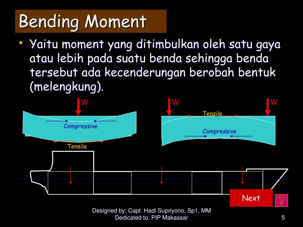
Bending merupakan fenomena yang terjadi ketika suatu benda mengalami gaya tekanan yang membuatnya melengkung atau menekuk. Pengertian bending dalam dunia konstruksi sangat penting untuk dipahami agar dapat merencanakan dan melaksanakan konstruksi yang aman dan kokoh.

MEKANIKA TEKNIK Pembahasan Modul 7 (Diagram gaya geser dan bending
A bending moment is a force normally measured in a force x length (e.g. kNm). Bending moments occur when a force is applied at a given distance away from a point of reference; causing a bending effect. In the most simple terms, a bending moment is basically a force that causes something to bend.
What is bending moment? Understand in simple terms
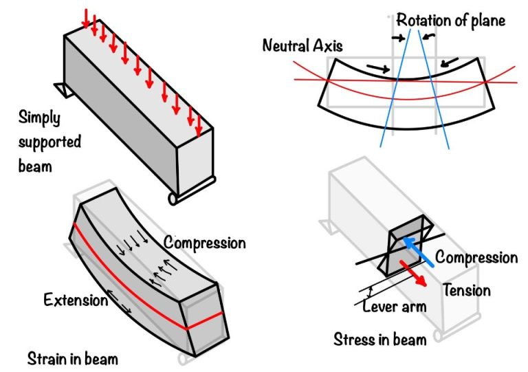
Relation between the radius of curvature, R, beam curvature, κ , and the strains within a beam subjected to a bending moment. The bending moment can thus be expressed as. M = ∫ y(EκydA) = κE ∫y2dA (7.3.2) (7.3.2) M = ∫ y ( E κ y d A) = κ E ∫ y 2 d A. This can be presented more compactly by defining I (the second moment of area , or.
Brief Information About Shear Force And Bending Moment Diagrams
In solid mechanics, a bending moment is the reaction induced in a structural element when an external force or moment is applied to the element, causing the element to bend. [1] [2] The most common or simplest structural element subjected to bending moments is the beam.